It’s a good feeling to kill two birds with one stone (figuratively) when delivering an IT project. I had the opportunity to do just that recently when two separate business units offered up two very different problems that I could solve at the same time. The first requirement was time synchronisation using PTPv2, or IEEE1588-2008 Precision Time Protocol, to synchronise devices in multiple buildings within our campus (approximately 2000 fibre route meters from end to end). The second requirement was an iSCSI network between the same locations for SAN replication between multiple pairs of disparate buildings.
Our current LAN network at the time just didn’t support PTP. I’m sure we could have made it work somehow by using multicast routing, but the sub 50 microsecond precision required for the application wouldn’t have been achievable. It was obvious that we needed some new switches. Initially I was looking at Cisco’s industrial switches since we already had some deployed in the network.
As for the iSCSI requirement, we needed multiple 10Gig uplinks to every SAN. Again, our current LAN network at the time didn’t have the capacity to accommodate that many 10Gig ports, so it was also apparent that new switches were required to run a separate SAN network.
After a lot of Googling for high density 10Gig switches, I came across some Nexus switches that also happened to support PTP. They had 32 x 10Gig SFP+ ports each. My thought process ended up something like: Ideal. WOW Expensive! Let’s try Ebay. Ideal.
We ended up buying 8 x Nexus 5548up switches from Ebay, with the L3 daughter board and L3 license (i’ll explain why later). The switches ended up costing around £1,500 each, instead of £25k+ per switch new.
To provide an accurate time source we also purchased a Meinberg GPS / GNSS PTP grandmaster clock. This also turned out to provide NTP as well, so our domain has a pretty precise time source now, but that’s a different story.
Physical Topology
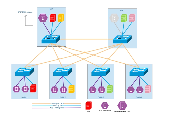
Now the topology of the switches is as follows.  We decided to go with this topology to allow us to add an additional grandmaster clock at a later date in the second “hub” location. Since both hubs are on different substations etc, this would provide some resilience if and when required. Wed also have an abundance of disparate fibre between all of the facilities and the two hubs, as these are are main datacenter locations.
PTP
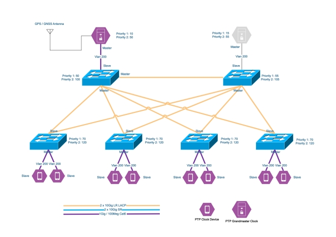
The PTP logical topology looks a little something like this.
Each switch is configured to be a boundary clock in the PTP domain. The PTP priorities of the switches mean that if the grandmaster goes offline for whatever reason, the switches will all synchronise to the lowest priority switch. This was done to ensure the equipment in all facilities were in sync with each other, even if they weren’t in sync with actual time. If a facility becomes isolated from he rest of the network, then at least its clocks will all remain in sync with each other since the switch in that facility has a lower priority than the default PTP priority.
The PTP ports are on a vlan local to the switch. Since the switches are boundary clock, there doesn’t need to be layer 2 adjacency between the grandmaster clock and the clocks (devices) for PTP to work. The port configuration is simple and is as follows.
You don’t even need to configure ip addresses on the local vlan. The devices will use link local addresses and multicast to communicate with the switch. No pesky VRF’s required!
iSCSI
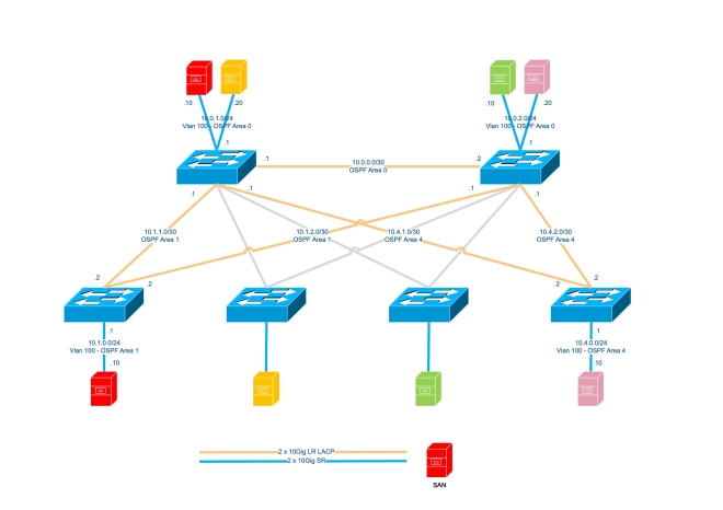
The iSCSI topology ended up being Layer 3 between the buildings. We didn’t want to stretch Vlan’s between the buildings to help contain outages. The operational facilities are test & validation facilities with a lot of moving mass or high voltage, so the likelihood of a switch being taken out is pretty high. To propagate routes we used OSPF, with the hubs being area 0 and each facility having it’s own area. The logical iSCSI topology looks like this. I’ve only included the information for two of the four facilities to make it more legible.
I’m aware that some people don’t like using layer 3 in iSCSI networks. In our situation, the replication is asynchronous. In each building the iSCSI initiator and target are both on the same subnet / vlan. Only the replication traverses layer 3 boundaries. We haven’t seen any performance or reliability issues with this topology yet so all is good.
Final Observations / Notes
One caveat of the Nexus 5548up switches is that the ports cannot run at 100Mbit/s. This is an issue for some PTP devices as they only have 100Mbit/s ports. To get around this we used cheap media converters from FS.com. These media converters will happily have a 1Gbit/s SFP in the SFP port, and a 100Mbit/s connection in the RJ45 port.
Another caveat of the Nexus 5548up switches is that if you want to run a port at 1Gbit/s with an RJ45 SFP, you must force the port to 1000Mbit before it will come up. Just add speed 1000 to the port configuration.
Buying Cisco SFP’s isn’t really worth it when using used switches. Even on Ebay a used one is around £35-60 and you don’t know what sort of environment it’s been in. FS.com sell compatible optics for £19 with a 5 year warranty.
We also purchased spare switches for a quick response to a failure. We could have doubled down and deployed two per facility, but didn’t think it was necessary. The clock devices only have a single port at the end of the day, and SAN replication can catch up.
That’s it. I just thought I’d share one of those little last minute projects that needs to be delivered on a tight budget.