Cossor 1035 MKIII
UPDATE 6/6/14 I decided to address a peculiar issue with this model, that the A1 channel (Y1) indicates + down! This is the primary channel having a bandwidth of 5MHz, also the trigger/sync is taken from this channel. The A2 (Y2) channel has a much smaller bandwidth of 250KHz however, the polarity can be inverted so at least both channels may be set to the same polarity! It should be remembered that even though this is the MKIII model, it was introduced in the early days of dual-trace oscilloscopes. Never-the-less, I cannot quite conceive why Cossor allowed this quirk to persist, especially since it does turn out to be easy to remedy. Most of the time, this quirk is not an issue however, it is odd when displaying calibration time marks. Since I did re-calibrate the timebase, I found this irritating since the polarity of the marks is very obvious (there is a picture of this further down this post). This design uses what may have been a technology unique to Cossor, a split-beam CRT so the Y channels are single-ended. This means that polarity cannot be simply inverted by swapping the Y amp phases to the deflection plates, however, it occurred to me that since the A2 channel can be inverted from the front panel, I could simply swap the A1 and A2 deflection plates. I had 2 concerns: 1 that the sensitivity of the plates might be different and 2 that lengthening the wire from the A1 channel so that it will reach around the CRT to what was the A2 plate might reduce the bandwidth. My concerns were groundless. The sensitivities turned out to be identical (25V/cm), as they should be since the structure of the CRT is symmetrical. I measured the bandwidth of the A1 channel as 6MHz, handsomely exceeding the specification. The most difficult aspect of this modification was reversing the A2 phase indication. This involved rotating one wafer of the A2 attenuator switch through 90. I had to make an adaptor plate to provide mounting holes at 90° to the main axis of the switch.
Here are some neat pictures of the beast working, showing off the excellent focus:
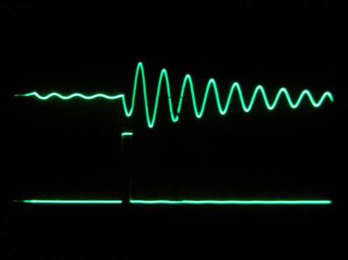
The oscillograms show a LC “pinger” stimulated using a pulse generator at 300PPS. The second oscillogram shows the stimulus expanded using the timebase delay.
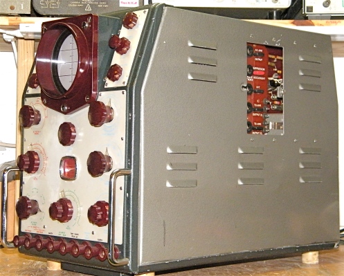
INTRODUCTION I had one of these when I was a kid. It was my first experience of a ‘proper’ oscilloscope, capable of making measurements and started my (admittedly eccentric) fascination with these machines. This was around 1974 and my dad, a Chartered Electronics Engineer and Senior Scientific Officer with the UK Met Office Cloud Physics lab, still used a Cossor 1035 MKIII at his development bench while the technicians were using Tek scopes. The original version when it was introduced, may have been the first dual-beam, triggered oscilloscope capable of making measurements. Since I wrote that, I found a June 1950 Wireless World advert for the original 1035 and from the picture I can see that it did not have the timebase delay that the MKIII has. Tektronix did not come out with a dual channel scope until the 530/535 in 1954 so Cossor did beat them to it. However, once Tek did bring the 530 series, everything else was in the shade. That it took HP 10 years to catch up (barely) really says it all for Tektronix. Anyway, here is the Cossor ad:  ARRIVAL. I had been wanting one of these and a guy in England contacted me saying he had just acquired one and was looking to sell it. The pictures showed a MKIII example in good condition so I took a chance on it and amazingly, just 5 days later, UPS arrived saying “we have a machine for you”. I unwrapped it with no little anticipation and was much relieved to find it undamaged. I think it is handsome, it is also surprisingly capable:
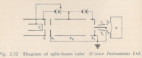
  SPLIT BEAM CRT. It is based on what as far as I know is a unique Cossor technology, the split-beam CRT. (A. C. Cossor got into business initially in 1859 as a manufacturer of scientific glassware, later X-ray tubes then vacuum tubes, diversifying into electronics after WW1.) The tube uses single Y plates that are placed either side of a beam splitter that is in mechanical and electrical contact with the final anode. The location of the Y plates either side of the splitter largely shields each beam from ‘fringing’ or interference by the opposite Y plate. The shielding is rendered perfect at the anode end by the contact with the final anode. At the screen end, fringing is reduced by means of two ‘bucking wires’ that are cross-connected to the opposite deflector plates and serve to annul the stray fields such that the interaction between beams is reduced to less than 1%. Correction for equal beam brightness is made using a small permanent magnet near the socket end of the tube that by deflecting the beam before it meets the splitter plate can be adjusted to obtain equal beam brightness. (Source: The Cathode Ray Tube And Its Applications, Parr and Davie.)
  I recall that the unit that I had as a kid exhibited the best beam definition I had ever known and this seems to be true, even the best of the Tek CRTs falls a little short and most, far short. It is simply beautiful to use.
CONDITION & REPAIR. Upon arrival, I found it to be fairly dirty inside, otherwise in excellent condition. I brushed the loose dirt away, I may wash it in the summer when there is strong sun to dry it. Then came the usually Deoxit treament of all the tube sockets. Next was to replacing the dried reservoir and smoothing caps (I disconnected them and checked them using a bench PSU). The flyback suppression coupling cap (visconol) was leaking oil so I replaced it right away. On turning it on I was rewarded with traces but a whole lot of hum showing. This turned out to be due to leaky coupling caps in the A1 amp causing heavy current draw that was pulling the B+ down hard enough to cause the regulator to drop out. Replacing those resulted in quiet traces and we were on our way! I wound up replacing most of the small paper in oil caps including the Plessey “toffee” types used for the timing of the timebase and delay circuits. They were all leaky causing extremely poor linearity:  The mains selector permits operation on 120 V so I fitted a new US style power cord. The only tube replacement required was the short suppressor base (in the US, dual-control) pentode used in the timebase. (These types have an unusually close wound suppressor grid to achieve the short base.) Cossor used a 6F33 which I replaced with a CV2209 (which I think may have been a special quality tube type for Racal). After taking care of these simple issues, I was able to calibrate it. Here it is displaying 1 mS markers and a squarewave that is synched to the markers:
  Note the great trace definition! The distortion at the start is due to a disadvantage of the transitron timebase, the Miller step, whereby the anode voltage drops a small amount suddenly at the initiation of the sweep. I say more about this under the design notes below.
PERFORMANCE & HISTORICAL CONTEXT. It has two AC coupled channels, the A1 channel having a response of 5 Hz to 5 MHz with a maximum sensitivity of 10 mV/cm; the A2 channel has a response of 5 Hz to 250 KHz with a maximum sensitivity of 1 V/cm. The timebase has 9 ranges, 100 mS to 10 µS. X expansion is available permitting a maximum spot velocity of 250 nS/cm. The reason the timebase ranges are stated as time not velocity is because the time ranges relate to a vernier scale on the X-shift; time is measured by setting the vernier at zero with the start of the event at a chosen location on the screen graticule, then using the vernier, sliding the end of the event to the same location. The time is given by multiplying the vernier reading by the time range is use. Voltage on the Y axis is measured using the same slide-vernier technique, the value of the event height read from the vernier is multiplied by the Y attenuator setting value in use to give the voltage. This method seems archaic but in use is very simple and easy. In fact, the timebase delay technology introduced by Tektronix handles magnified event measurement in the same way. At that time, nobody had introduced regulated CRT HV supplies and this was a good way to avoid the effect of HV voltage related CRT sensitivity variation on measurement accuracy. (Again Tektronix introduced CRT supply regulation.) Timebase delay is also included to permit event expansion, such as the viewing and measurement of the whole of a pulse across the screen width. The specification states that it will measure time and voltage to better than 10% which nowadays in our Parts Per Million world sounds hopeless, but in those days of oscilloscopes that were not capable of calibration was good news! In my estimation I would say it is better than 5%, not far short of the new standard set by Tektronix. I don’t know when the first 1035 MKI model was released but it must have been around or maybe slightly before the ground-breaking Tektronix scopes first became available. Unlike the first Tektronix, the 511, this one has regulated power supplies, absolutely unheard of before then. Tektronix did not regulate the power supplies in their scopes until the 511A. The timebase is a triggerable sweep duration rather than frequency design and this permits time measurement without resorting to a marker generator. It can be operated in triggered or repetitive modes.
8/8/14, I noticed that the specification says that it will trigger on a 1cm sinewave up to 5MHz which is a bold claim. Even Tek scopes of the era did not claim that and had a HF sync setting to bypass the trigger. Well, this was a challenge and at first, the scope could not match the claim in fact the trigger signal at 5MHz was mostly noise. Not surprisingly, it would barely synchronise and definitely would not trigger. The tubes in the trigger path and timebase were good. I fiddled around and scratched my head, finally replacing two carbon grid stoppers in the trigger path with new carbon films of much reduced value. Success, it does indeed trigger on a 1cm signal at 5MHz!
Here is the first reference that I have found to the timebase design again, from Parr and Davies: 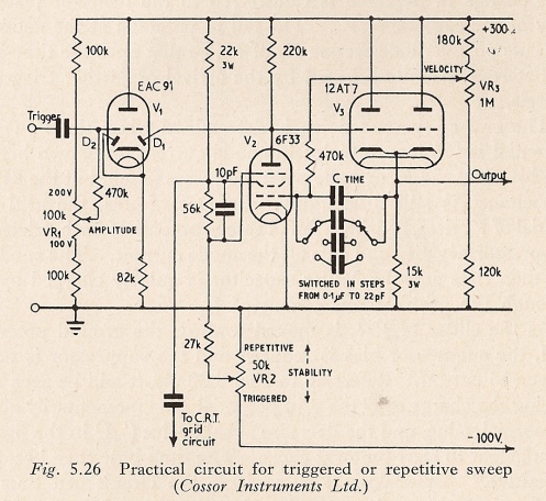 Martin on the british Vintage Test Gear & Workshop Equipment forum pointed out the the EAC91 specified is a single diode triode, it looks like an error and may have been intended to be EBC91, thanks Martin!
WHAT IT LOOKS LIKE INSIDE. Before I get into a more detailed technical description, here are pictures of it with the covers off, there is a lot of space due to the original design having used octal tubes! 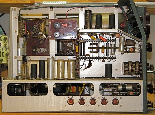 The A1 amplifier is on the shelf while the A2 amplifier is on the deck at the front. The power supply regulators are on the deck at the back.
  The timebase occupies the front section with the CRT circuit at the back.
  Note the handsome potted double C core power transformer! I also like the Colvern ganged wirewound precision potentiometers used for the measurement vernier scales.
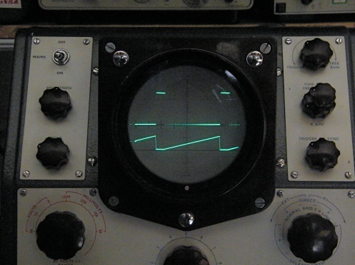
  DESIGN NOTES. Cathode Ray Tube. The design is based on a Cossor split beam, flat face CRT, the major consequence of which is that the Y amplifiers (referred to in the manual as A1 and A2) are single ended. This might sound like a major compromise and in comparison with more modern designs I suppose it is however, in use, the amps seem to provide highly accurate, symmetrical traces. Despite the lack of common mode rejection or DC heater supplies the traces are perfectly free from visible noise. The X and Y deflection plates are available for direct connection via slide doors in the oscilloscope cabinet. The cathode is operating at -2kV with the first and final anodes at ground potential. A Post Deflection Acceleration anode is provided, normally run at +350V with provision to increase the PDA to 2kV when extra brightness is required. All deflection plates are run at DC ground potential to minimise trace distortion. The focus is exceptional despite the lack of astigmatism correction. Here is another picture of it showing gate and sweep waveforms from a Tek scope:
  Power Supplies. The basis of the power supply is a beautiful potted C core transformer. A single 330-0-330 winding serves both the positive and the negative rails, the positive rectifier being a tube and the negative side is handled by two selenium rectifiers. The positive side is LC smoothed to provide a +350 V rail that feeds a classic series regulator having a triode connected pentode for the series pass element and a pentode error amplifier. The regulator supplies +200 V to most of the circuits in the scope. The negative side is RC smoothed to a -300 V rail and a gas tube stabilised -150V rail that also serves as the reference for the +200 V regulator. The CRT supplies are taken from a single HV winding and recified using selenium sticks both ways to provide plus and minus 2 kV, these supplies are RC smoothed.
Making Measurements. At this point, it is appropriate to further expound on the vernier-shift measurement technique used for both time and voltage measurements on this oscilloscope. Here is a diagram showing the electrical arrangement: 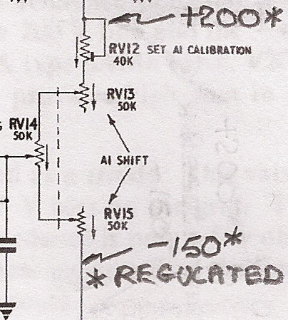 The method of measurement is; set the cursor of the appropriate vernier to zero on the scale on the panel, then use the shift potentiometer to set the lower (voltage measurements) or left (time measurements) part of the event to a chosen location on the graticule, usually the centre. Then operate the vernier until the other end of the event is at the chosen location. Read the value on vernier scale under the cursor and then multiply by the voltage or time range setting to give the voltage or time value. The two variable resistors RV13 & RV15 are a ganged pair that comprise the shift control, the wiper of RV13 is connected to the vernier potentiometer RV14, while the wiper of RV15 is connected to the other end of the vernier potentiometer, the shift potential being taken from the wiper of RV14. RV13 & RV15 have no scale, they allow the beam to be shifted by moving the entire vernier pot up and down electrically whilst maintaining a constant potential across the vernier pot and thus, the calibration of the vernier scale. The vernier-shift network is fed from regulated supplies to maintain calibration. The calibration is accomplished using RV12 whereby changing the setting of RV12 will change the potential across the network and thus the vernier pot, changing the amount the beam moves for a given movement of the vernier pot. RV12 is manipulated until the vernier scale accurately corresponds with a known voltage or time being displayed. For example, if the attenuator is set at 5 and a 5 V p-p event is on the screen, with the upper peak on the centre and the cursor at zero, then shifting it downward from zero using the vernier until the lower peak is at the centre should place the cursor over 5 on the scale. The graticule is engraved on both sides that in combination with the flat screen makes it easy to avoid parallax error. It should be noted that due to the Miller Step, Cossor recommended avoiding the first 10% of the trace when making time measurements. Physically, the vernier pot is mounted at the front of the shift pair and operated by a spindle that runs coaxially around the spindle of the shift pair control spindle and has a nice hairline cursor knob over a vernier scale that is printed on the front panel. The spindle of the shift pair emerges at a simple small control knob in the centre of the vernier. Here is what the controls look like:
 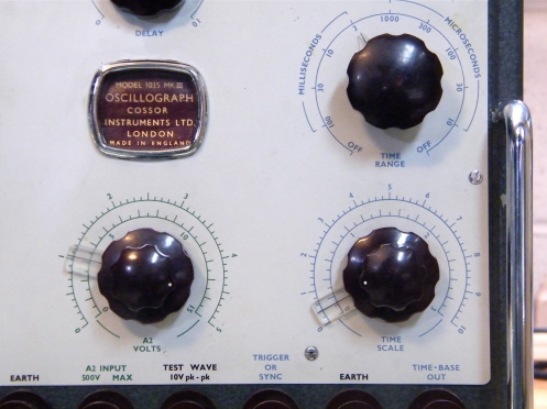 The beautiful Colvern wirewound pots used for these controls are sufficiently linear that the use of a printed scale works very well. This is in marked contrast to the silly printed scales on the front panel of toy oscilloscopes!
Y Amplifiers. The A1 amplifier is the primary Y channel and the trigger / synch signal is taken from this channel. One aspect that is odd is that the A1 deflection is positive down, I would love to know the design rationale for this arrangement…….. It is not as if there were any lack of awareness, the polarity is marked on the front panel, also the triggering polarity is correct, on +, the trace starts on a falling edge and on – it starts on a rising edge, which is correct but confusing. This issue could have been overcome by swapping the A1 and A2 deflection plates (as I ended up doing).
The A2 amplifier is a simple differential pair and phase reversal is provided on the range switch so if the Y deflection plates were swapped, it would have been simple to have the panel phase marking for the A2 channel correct. Both channels are AC coupled which is a significant downside, probably necessary to avoid DC drift in the single ended amplifiers that would be hard to eliminate despite the use of regulated power supplies. The A1 amplifier has a maximum gain of 3000 (69.5dB). It uses three RC connected pentodes and what the manual describes as “heavy negative feedback”. Each stage has adjustable bias, the bias and all plates and screens are fed from the regulated supplies except the final stage plate which is fed from the LC smoothed 350V supply. Seven switched HF compensated attenuation levels provide sensitivities from 10 mV/cm to 10 V/cm. The frequency response on all ranges except the 50 mV (10 mV/cm) range is 5 MHz at -3dB. An additional attenuator available as a separate input socket that extends the range to 300 V/cm. The A2 amplifier is a single stage differential pair, permitting phase reversal. The gain is 300 (49.5dB) and with 5 HF compensated attenuation settings provides sensitivities from 1 V/cm to 100V/cm, with a bandwidth of 250 KHz. Clearly the A1 and A2 channels were expected to service very different needs! However, for audio and other lower frequency work, it is possible to compare two signals by superposing them. You may have noticed that this machine has very old world connectors, designed for banana plugs and also for bare wires by means of a cross hole and a sprung shroud. They are very nice but not practical, at least in my lab, so I made a BNC adaptor plate for the A1 & A2 channels: 

X Amplifier. The X amplifier provides symmetrical deflection and shift by means of a pentode differential pair. To minimise trace distortion, the anodes are DC coupled to the X plates via 3 Hivac neons in each phase that bring the plates close to ground potential. Shunt capacitors are included because the impedance of the neons rises with frequency; a series resistor is placed in each neon chain to prevent relaxation oscillation. The bandwidth of the X amplifier is -3dB at 200kHz. HF compensation is provided on the coupling network to the timebase. The gain is variable from the front panel by the provision of a variable resistance between the cathode resistors that are returned to -300V rail. The variable gain makes it possible to greatly expand an event without changing the time calibration because the time vernier-shift is applied to the input grid of the amplifier.
Synch Phase, Amplifier and Limiter and TV Synch Separator. The synch signal is picked off a tap in the anode load of the final stage of the A1 amplifier. This feeds a cathodyne stage that permits the user to select synch/trigger off positive going or negative going signals. The next stage uses a pentode that is run with its screen to a low voltage to give a short grid base. No bias is provided and so the stage will clip negative going signals at the grid and not pass positive going signals at the grid producing a clipped positive going pulse at the plate (the stage inverts) that is further amplified and inverted once again to produce a negative going pulse used to synchronise or trigger the timebase, depending on the timebase stability setting. (This also has the effect of removing positive going video content from composite TV signals. Along with this, a TV frame position of the synch control is available that passes the signal though a circuit that discriminates TV frame synch signals such that only the TV frame synch signals are passed to the timebase. (I would think that this scope then, was at least in part, aimed at TV development.)
TimeBase. Written with much help from Parr and Davies, Refer to the diagram below: The operation is best considered by considering it in the triggerable condition. During the quiescent or ‘top’ period, the suppressor grid of V11 (the 6F33 short suppressor base pentode) is biased beyond cut-off by the negative setting of RV18, the trig / free-run control. In this state, the cathode current flows to the screen grid. The plate potential which would normally rise to 350V (since plate current is cut-off by the suppressor) is clamped by the potential of the diode, V10A which is connected to the cathode of the cathode follower, V9A. (The actual value of this potential is controlled by the front panel timebase frequency control, more on this further on….) V9A presents a high impedance to the trigger signal that is applied to its grid and a low impedance to the cathode of the diode, V10A. So, the circuit is in its ‘top’ state, awaiting the trigger to cause it to run-down. When a negative triggering pulse is applied to the grid of V9A, this pulse appears at the plate of V10A and it is passed to the grid of V12A by way of the plate of V11. From the cathode of V12A, it is applied by the Miller capacitance (the timing capacitors) to the grid of the Miller Transitron tube, V11. (The amplitude of the pulse should not exceed the grid base of V11 or it will distort the run-down, known as over-triggering. This amplitude can be controlled by the sync control on the front panel to prevent over triggering.) The resulting negative going potential at the grid of V11 causes the screen potential to rise and since it is connected to the suppressor grid by way of R94 also drives the suppressor grid positive allowing plate current to flow and so the tube transitions (hence transitron) from not conducting to conducting. Since the suppressor current is diverted from the screen current, the screen potential will rise further and a bootstrap action takes place. The potential of the V11 plate follows the Miller run-down and is taken off to the X amplifier by way of the cathode of the cathode follower, V12A. The fall in V11 plate potential cuts off the diode, V10A and so once the run-down has started, it will not be affected by the arrival of triggering signals during the run down. The end of the run-down is determined when the plate of V11 is too low to maintain plate current, at this point the cathode of V12A ceases to fall, but the Miller capacitance (timing capacitor) is still discharging. Since the cathode end of the Miller capacitance cannot drop further in potential, the V11 grid end of the Miller capacitance V11 rises causing a fall in screen current which drives the screen negative and cuts off the plate current. The Plate of V11 then rises and the Miller capacitance is quickly recharged (flyback) by the grid-cathode circuit of V12A until the plate of V11 reaches the clamp potential due to the cathode potential of V9A acting via the clamp diode, V10A. The circuit is now at the ‘top’ ready to re-start. It can be seen in the oscillogram below that once the Miller step has happened, the run-down is very linear. This is because the run-down at the plate is also “seen” by the grid via the Miller capacitance, refer to the oscillogram below. Cossor noted in their manual that the plate of V11 is returned to the +350V rail allowing a high value of plate load, thus increasing the gain in the feedback loop. They also note that the use of a cathode follower in the plate-grid circuit reduces flyback time due to the low impedance at the cathode of V11 resulting in faster recharge. It follows that as the trig / free-run is adjusted so that the suppressor of V11 is moved positive until V11 is conducting, the circuit will free-run. The function of V10B is to prevent suppressor current by limiting how far positive the suppressor potential can rise. The 6F33 and CV2209 have an internal diode for this purpose and Cossor included V10B to “assist” the internal diode probably because there was a second otherwise unused diode available in theEB91 envelope! A very novel feature of this design is that the free-run repetition rate is controlled by the ‘top’ voltage which is set by the cathode potential of V9A. The DC potential of the grid of V9A can be controlled from the front panel using the timebase frequency control and as the ‘top’ voltage is reduced, the run-down potential change is also reduced resulting in the timebase repeating at a faster rate. Note, the actual run-down rate is fixed and determines the timing calibration. So if the operator increases the timebase frequency, he will be rewarded with a shorter timebase, to the point where it actually stops! I did not understand this when I was a kid and I have read somebody querying it on one of the forums. It appears and perhaps is, wierd. However, the actual length of the oscillogram can be increased using the X amplifier control on the front panel, as described above and so it is helpful in obtaining one or two cycle oscillograms that occupy the entire screen which is useful for photography and single stroke working. Here is the circuit as promised:  Here are oscillograms of this timebase taken on a Tektronix 547A: The sweep rate is 2mS/cm and from the top we have: 100 V/cm, Run-down at the plate of V11, you can see the Miller Step at the start of the run-down. 10 V/cm, V11 grid waveform, you can see the negative bump due to the trigger pulse and the run-up which is the negative feedback that causes excellent linearity. 100 V/cm, V11 suppressor waveform (used for flyback suppression or trig bright-up) 20 V/cm, Trigger pulse at the cathode of V10A, run-down starts at the negative going edge, you can see how the run-down is unaffected by further trigger pulses during the run-down.
Flyback Suppression & Trig Bright-Up. The square pulse that is available at the screen grid (see the oscillogram above) of the transitron tube is negative going during flyback and when applied to the grid of the CRT causes suppression of the trace during flyback. The screen grid pulse is also square during the sweep and positive going. By applying this positive going sweep pulse to the cathode of the CRT, it can be used to unblank the CRT during the sweep, my father termed this “trig bright-up”. On this scope, it is possible to readily change it to blank/unblank by means of a link on a side panel and it works very nicely. The advantage of this mode is that there will never be bright stationary dots (that can burn the screen) when the timebase is not running as is the case in triggered mode when there is no signal present on the A1 channel. The disadvantage is the AC coupling time-constant, which will cause the trace to dim towards the end of the sweep at lower sweep speeds.* I have found that when working above 200 Hz or so, it is not a problem so I have my unit in trig bright-up mode. * This is the reason Tektronix developed DC coupled unblanking, I think this was done by John Kobbe. I have come across many very ingenious alternative techniques, developed by other manufacturers who were seeking to avoid paying license fees to Tektronix!
Timebase Delay. Timebase delay is introduced by switching in a delay circuit between the sync clipper and the timebase that generates a secondary pulse that is used to trigger the timebase. It is a mono-stable multivibrator that is tripped by a potential developed across a RC charging circuit. On receipt of a trigger pulse, the circuit commences to charge, the rate of charge being controlled by the operator by varying the resistance in the circuit using the delay control on the front panel. One the charge potential reaches the trip point, the circuit produces a sharp edged pulse that is uses to trigger the timebase. The delay can be increased up to at least 10 times the timebase speed in use. A diode is included in the grid circuit that cuts off when the circuit trips and remains cut-off until the circuit approaches the trip point, blocking any subsequent trigger pulses that will arrive as the circuit re-charges. The delay capacitors are switched with the timebase range switch to maintain the correct relationship between timebase speed and delay time. Being mono-stable, it automatically resets each time it trips. The reset action speed limits its use to a repetition rate of less than 100 kHz. This feature enables the whole of a single pulse from a repetitive pulse signal to be measured without the Miller step affecting the measurement. For example if a pulse of 1 µS and 1000 Hz repetition rate is to be observed, put the time switch to 100 µS and the timebase in trigger mode. Set the time vernier to zero and use the delay control to place the start of the pulse at the centre of the graticule. Then use the vernier to bring the end of the pulse to the centre of the graticule, read the vernier and multiply by the time range in use, this will give the duration of the pulse.
Simply Impressive!
Thank you Lars, the post or the scope or both? 🙂
Great to the see the scope back in action, highly informative post !!!
Hi Jon.
Well I greatly appreciate the opportunity you gave me to acquire it and the care and despatch with which you sent it!
I have posted about it only a couple of vintage electronics forums asking for historical information. I would like to know when it was introduced,the MKI also.
Best, Richard
I love the site, and I love the detailed article. Keep it up!
Hi Jake
Thanks! Will try to do so.
we are manufacture, exporter and suppliers of Fluid Mechanics Lab Equipment in india since 1954 with a range of Technical Educational Equipment equipment.with a range
of Technical Educational Equipment equipment we are the top Fluid Mechanics Lab Equipment manufacturer, exporter and suppliers in India click more
Hmmm. I don’t usually approve commercial comments however, I went to their site and am quite impressed, it is a kind of virtual fluid mechanics science museum.