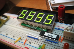
A while back I purchased an I2C compatible 4-digit seven-segment module on eBay for next to nothing. The description said arduino compatible, so getting it to work with PICS should not be a problem. The display module is based on NXP SAA1064 I2C controller. The datasheet for the SAA1064 can be found here. The modules I2C device address is factory-set at %01110000, or $70. Initially, I2CWRITE seemed like the logical choice for getting the device to work. For some reason I was unable to get I2CWRITE to work, and had to manually send commands via the SHIFTIN/SHIFOUT commands. After the 16F88 was up and running on the breadboard, went about hooking up the module. There are 4 pins on the board: VCC, SDA,SCL,GND. VCC and GND were connected to their respective pins. The SDA and SCL pins were then connected to PICs B.2 and B.3 pins with pullup resistors on both pins.
Before the module can display anything the SAA1064 has to be initialized.
First the I2c communication has to be started, which accomplished by calling the subroutine I2C_START:
 I2C_START:
    HIGH SDA
    HIGH SCL
    LOW SDA
   RETURN
The SDA and SCL pins are both set HIGH, then the SDA is brought LOW, which lets the I2C bus know data is comming.
The SAA1064 expects the next byte to be the device byte, followed by the instruction byte, followed by either a control or data byte. When the circuit is first powered on the SAA1064 must be initalized. So first the device byte is sent:
i2c_out = %01110000 : GOSUB I2C_TX
The program contains a variable i2c_out, that gets loaded with the byte to be shifted out. The subroutine I2C_TX is then used to shift that data out:
I2C_TX:
    SHIFTOUT SDA,SCL,1,[i2c_out]
    SHIFTIN SDA,SCL,0,[i2c_ack\1]
    RETURN
SHIFTOUT is used to send the i2c_out byte, MSB first. Next SHIFTIN is used to recieve the ACK bit from the SAA1064.
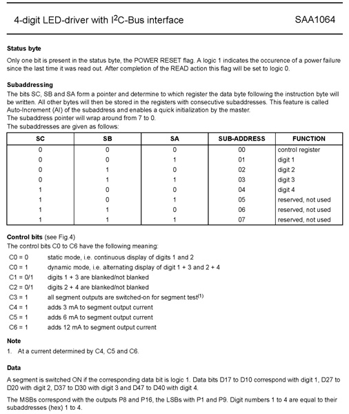
Next the instruction byte needs to be sent. Refer to the datasheet for bit settings of the instruction byte.

The instruction byte is like a pointer to where the next byte is put on the SAA1064. A value of %00000000 sets the pointer to the control register. So the i2c_out is loaded with %00000000 and shifted out:
i2c_out = %00000000 : GOSUB I2C_TX
Now that the pointer is set to the control register, the control byte can be sent. The control byte allows different settings of the chip to be used. A value of %00010111 turns on dynamic mode, turn off blanking on segments 1-4, and sets the segment power at 3mA. So again the i2c_out variable is loaded with %00010111 and shifted out:
i2c_out = %00010111 : GOSUB I2C_TX
Now that the control byte is sent, the I2C communication can be ended by calling the I2C_STOP subroutine:
I2C_STOP:
    HIGH SCL
    HIGH SDA
    PAUSE 1
   RETURN
The I2C_STOP subroutine brings the SDA pin high again which ends the I2C transmission. Now the display is set up and is ready to use. A simple example of use:
First use LOOKUP to translate segment bits into actual decimal numbers. This is where things could be different depending on who built your module. Mine came with a segment key:
0 = b
1 = DP
2 = a
3 = c
4 = e
5 = d
6 = g
7 = f
So using a lookup table, bits can be translated into digits:
LOOKUP i, [189,9,117,109,201,236,248,13,253,205],seg_val
If the value (4) is loaded into the i variable, then the LOOKUP command would load (201) into the seg_val variable. (201) is the decimal equvilant of %11001001, which turns on segments f,g,c,and b; or the number (4) on the display. Now the value can be sent to the display:
GOSUB I2C_START
   i2c_out = %01110000 : gosub i2C_tx 'device byte is sent
   i2c_out = %00000001 : gosub i2C_tx 'instruction byte is set to point to digit 1
   i2c_out = seg_val : gosub i2c_tx 'seg_val is sent to display
GOSUB I2C_STOP
First the I2C transmission is started. Then the device byte is sent, followed by the instruction byte %00000001, which sets the pointer to the first digit. Then seg_val is then sent. Finally the I2C transmission is stopped, and the number 4 should be displayed.
I cant seem to get the auto increment to work, so each digit has to be pointed to manually with the instruction byte.
Here is the entire PICBASIC code for a PIC16F88, which counts from 0-9, on each of the digits:
-------------------------------------------------------------------------------
'// for 4MHZ
DEFINE OSC 4
OSCCON=%01101000
'// for 8MHZ
'DEFINE OSC 8
'OSCCON=%01111000
While OSCCON.2=0:Wend
CMCON         =  7                 '// PORTA = digital I/O
'OPTION_REG.7  =  0                 '// Enable PORTB pull-ups
ADCON1        =  7
ANSEL=%00000000                    '// set all analog pins to digital
ANSEL = 0                          '// disable ADCs
TRISB.3 = 0
TRISB.2 = 0
'----------------------------------------------------------------------------
led         var PORTA.1
SDA         VAR PORTB.3
SCL         VAR PORTB.2

i2c_out     VAR BYTE        'data to sent over I2C bus
i2c_ack     VAR BIT         'acknowledgement bit
i           var byte
segment     VAR byte
seg_val     var byte
'----------------------------------------------------------------------------
gosub startup
GOSUB init_display   'initialize the display module
main:
   GOSUB COUNTER
   goto main
   END

counter:
    for i = 0 to 9
        lookup i, [189,9,117,109,201,236,248,13,253,205],seg_val
        for segment = 1 to 4
              GOSUB I2C_START
              if segment = 1 then
                 i2c_out = %01110000 : gosub i2C_tx : i2c_out = %00000001 : gosub i2C_tx
                 i2c_out = seg_val : gosub i2c_tx
                 gosub i2c_stop
              endif
              if segment = 2 then
                 i2c_out = %01110000 : gosub i2C_tx : i2c_out = %00000010 : gosub i2C_tx
                 i2c_out = seg_val : gosub i2c_tx
                 gosub i2c_stop
              endif
              if segment = 3 then
                 i2c_out = %01110000 : gosub i2C_tx : i2c_out = %00000011 : gosub i2C_tx
                 i2c_out = seg_val : gosub i2c_tx
                 gosub i2c_stop
              endif
              if segment = 4 then
                 i2c_out = %01110000 : gosub i2C_tx : i2c_out = %00000100 : gosub i2C_tx
                 i2c_out = seg_val : gosub i2c_tx
                 gosub i2c_stop
              endif
          next segment
        pause 100
      next i
    return
init_display:           'initialize the SAA1064 module and flash all segments
    GOSUB I2C_START     'Start the I2C communication
       i2c_out = %01110000 : GOSUB I2C_TX        'send device byte
       i2c_out = %00000000 : GOSUB I2C_TX        'send instruction byte
       i2c_out = %00011111 : GOSUB I2C_TX        'send control byte
    GOSUB I2C_STOP      'Stop i2C transmission
    pause 1000          ' leave segments on for 1 sec then turn off

    GOSUB I2C_START
       i2c_out = %01110000 : gosub i2C_tx
       i2c_out = %00000000 : gosub i2C_tx
       i2c_out = %00000001 : GOSUB I2C_TX
    GOSUB I2C_STOP
    pause 500

    GOSUB I2C_START
       i2c_out = %01110000 : gosub i2C_tx
       i2c_out = %00000000 : gosub i2C_tx
       i2c_out = %00010111 : GOSUB I2C_TX
    GOSUB I2C_STOP
  RETURN
I2C_START:
    HIGH SDA
    HIGH SCL
    LOW SDA
   RETURN

I2C_STOP:               'I2C stop (terminate communication on I2C bus)
    HIGH SCL
    HIGH SDA
    PAUSE 1
    RETURN

I2C_TX:                           'I2C transmit -> send data to the slave
    SHIFTOUT SDA,SCL,1,[i2c_out]  'Shift out “i2c_out” MSBfirst
    SHIFTIN SDA,SCL,0,[i2c_ack\1] 'Receive ACK bit
    RETURN
--------------------------------------------------------------

